友情提示点击顶部放大镜 可以使用站内搜索 记住我们的地址 www.hainabaike.com

MAKER:Arduino
心愿球
由黄铜棒制成,采用自由球形态连接 18 颗发光 LED。
硬件材料
1*黄铜棒
18*贴片 LED
1*ATmega8L 芯片
1*CR2032 纽扣电池
1*开关
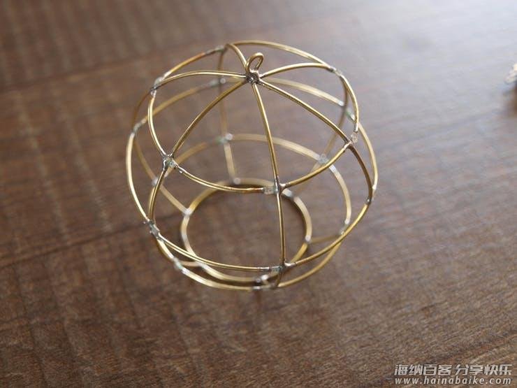
天体
主要挑战是用黄铜棒弯成圆形,看起来像一个天体。我用 6 根铜棒竖直排列(经度)和 3 根铜棒水平排列(纬度)构建一个球。这样子就总共有 18 个交叉点用于焊接 LED。在球体的底部有一个环形开口,为的是最终可以更好的放入芯片、电池等元器件。
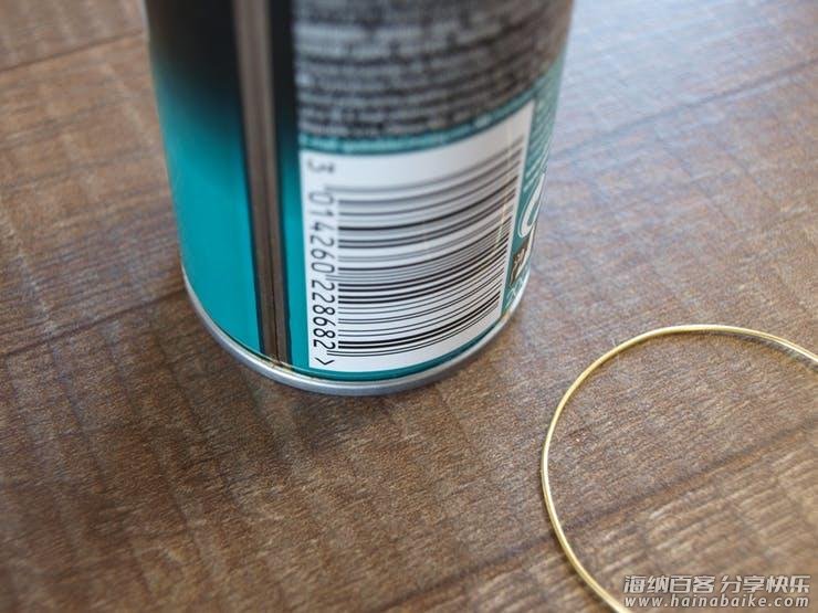
首先,把铜棒弯成圆形。我最开始找到一个直径为 50 毫米的铁罐,可以在弯曲时用底盖固定铜棒。弯曲铜棒后,把其剪断并把两端焊接在一起,形成一个漂亮的环。在一张纸上画出相同的形状,可以帮助你匹配最完美的圆形。为了制作更小的圆环,我使用了其他直径的瓶。使用与你的直径相匹配的东西,身边上到处都是圆形的东西!
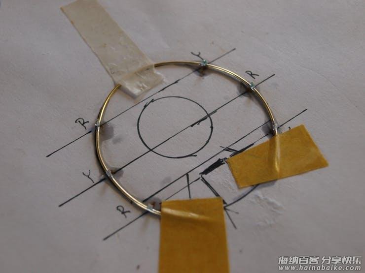
接下来,我把 LED 焊接到三个 50mm 环上。我在一张纸上画了一个模板。我采用是黄色和红色LED。黄色和红色,因为它比蓝色或白色更节能。
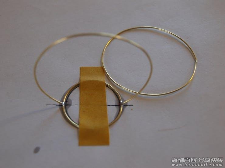
接着,我把带有 LED 的环焊接到基环上。我用一块胶带把基环固定在桌子上,修剪了垂直环的底部并把它们焊接到环上,形成了一个皇冠。第一个环焊接成一体,第二个和第三个环切成两半,形成球体的平顶。
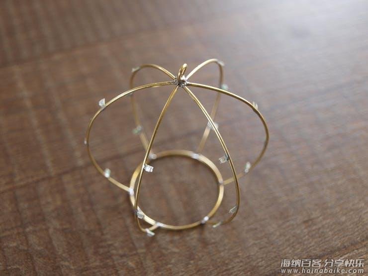
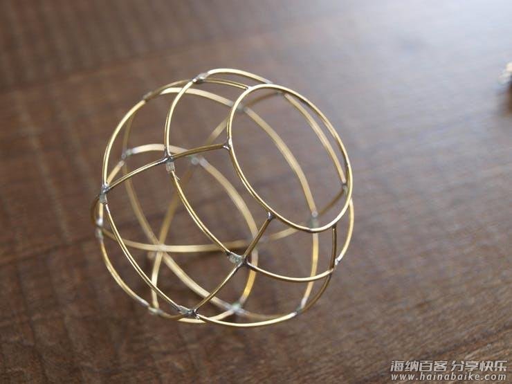
最后一步是最让人沮丧和耗时的。把 LED 与弯曲杆相互连接以形成水平环。我把剩下的环一个一个地切开,以适应垂直环之间的空间并求佛一样地焊接。
我想到一种放置 LED 的简单方法。 两个 LED 在邻近的垂直环(地面)上彼此面对,它们与一根弯曲的杆连接,该杆是水平环(电源线)的一部分。最终得到 18 个 LED,分为 9 个部分。
温馨提醒:经常测试 LED 是否仍是好的,否则你需要在最后重做这件事,这是一种可怕的又振奋人心的测试。
如果你只是希望它发光并且不关心任何动画。你可以立即停止阅读,把 CR2032 纽扣电池和开关放入内部。通过 68Ω 限流电阻把 LED 与电池连接,就可以使其发光!把电池焊接到黄铜线时,请确保不要过热,否则可能会导致电池过热。
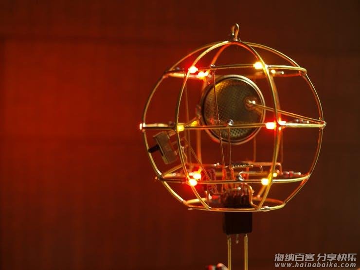
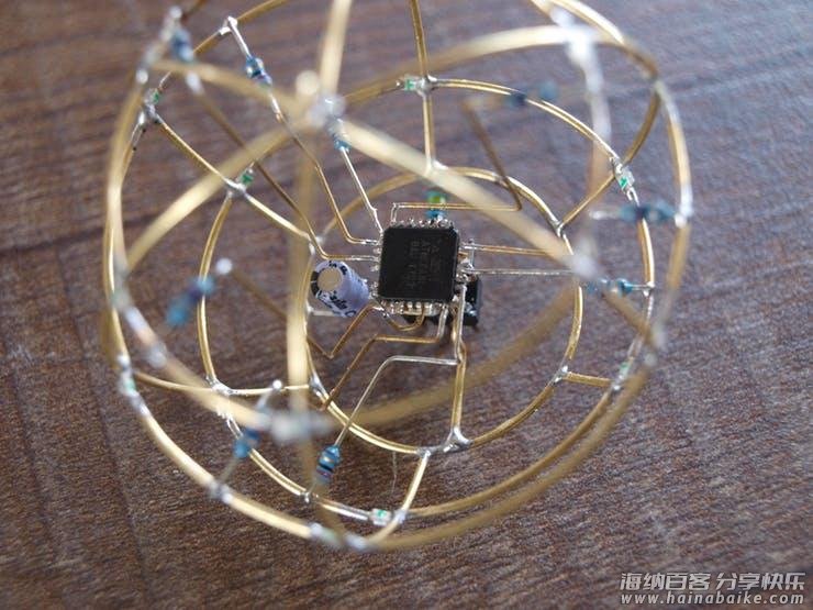
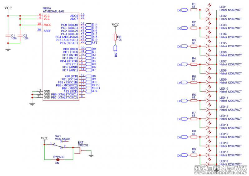
如果你像我一样,爱 Arduino 并希望让它变得聪明并且有一点乐趣,让我们把微控制器放入其中!我使用的是 ATmega8L 芯片——与 Arduino NANO 相同的封装,但内存更少,功耗更低。L 意味着它具有 2.7 – 5V 的宽工作电压范围,这在使用 3V 纽扣电池时非常棒。另一方面,由于它是TQF32 封装,因此焊接到铜棒上是一个不小的挑战,但外观和效果都很好。
原理图
源代码
#define LEDS 9

byte leds[] = {
  5, 19, 17, // bottom
  6, 1, 15, // middle
  8, 21, 13 // top
};

#define ON true
#define OFF false

// variables for pattern timing
unsigned long currentMillis = millis();
unsigned long previousMillis = 0;
unsigned long millisInterval = 3
00;

// variables for software PWM
unsigned long currentMicros = micros();
unsigned long previousMicros = 0;
// this is the frequency of the sw PWM
// frequency = 1/(2 * microInterval)
unsigned long microInterval = 250;

const byte pwmMax = 100;

// fading (for the timing)
int fadeIncrement = 1;

// typedef for properties of each sw pwm pin
typedef struct pwmPins {
  int pin;
  int pwmValue;
  bool pinState;
  int pwmTickCount;
} pwmPin;

// create the sw pwm pins
// these can be any I/O pin
// that can be set to output!
const int pinCount = 9;
const byte pins[pinCount] = {
  5, 19, 17, // bottom
  6, 1, 15, // middle
  8, 21, 13 // top
};

pwmPin myPWMpins[pinCount];

// function to "setup" the sw pwm pin states
// modify to suit your needs
// this creates an alternating fade pattern
void setupPWMpins() {
  for (int index=0; index < pinCount; index++) {
    myPWMpins[index].pin = pins[index];

    // mix it up a little bit
    // changes the starting pwmValue for odd and even
    if (index % 2)
      myPWMpins[index].pwmValue = 25;
    else
      myPWMpins[index].pwmValue = 75;

    myPWMpins[index].pinState = ON;
    myPWMpins[index].pwmTickCount = 0;

    // unlike analogWrite(), this is necessary
    pinMode(pins[index], OUTPUT);
  }
}

void pwmFadePattern() {
  // go through each sw pwm pin, and increase
  // the pwm value. this would be like
  // calling analogWrite() on each hw pwm pin
  for (int index=0; index < pinCount; index++) {
    myPWMpins[index].pwmValue += fadeIncrement;
    if (myPWMpins[index].pwmValue > 100)
      myPWMpins[index].pwmValue = 0;
  }
}

void handlePWM() {
  currentMicros = micros();
  // check to see if we need to increment our PWM counters yet
    if (currentMicros - previousMicros >= microInterval) {
    // Increment each pin's counter
    for (int index=0; index < pinCount; index++) {
    // each pin has its own tickCounter
      myPWMpins[index].pwmTickCount++;

    // determine if we're counting on or off time
      if (myPWMpins[index].pinState == ON) {
        // see if we hit the desired on percentage
        // not as precise as 255 or 1024, but easier to do math
        if (myPWMpins[index].pwmTickCount >= myPWMpins[index].pwmValue) {
          myPWMpins[index].pinState = OFF;
        }
      } else {
        // if it isn't on, it is off
        if (myPWMpins[index].pwmTickCount >= pwmMax) {
          myPWMpins[index].pinState = ON;
          myPWMpins[index].pwmTickCount = 0;
        }
      }
      // could probably use some bitwise optimization here, digitalWrite()
      // really slows things down after 10 pins.
      digitalWrite(myPWMpins[index].pin, myPWMpins[index].pinState);
    }
    // reset the micros() tick counter.
    digitalWrite(13, !digitalRead(13));
    previousMicros = currentMicros;
  }
}

void setup() {
  setupPWMpins();
  //pinMode(13, OUTPUT);
}

void loop() {
  // this is the magic for sw pwm
  // need to call this anytime you
  // have a long operation
  handlePWM();

  // check timer for fading pattern
  // this would be the same
  // if we used analogWrite()
  currentMillis = millis();
  if (currentMillis - previousMillis >= millisInterval) {
    // moved to own funciton for clarity
    pwmFadePattern();

    // setup clock for next tick
    previousMillis = currentMillis;
  }
}
via http://bbs.nxez.com/thread-453-1-1.html


评论列表